Table of Contents
Model Type: FlatPanel 1.4
General Knowledge of How a 5-Piece Furniture Door (Model Type: FlatPanel) Is Constructed
Components
The typical furniture door (frame-and-panel style) is constructed from five main components:
- Stiles (2 pieces) named in Figure 2 B4 and B2: These are the vertical members of the frame. They run the full height of the door and are usually fixed in place.
- Rails (2 pieces named) B1 and B3 named in Figure 2: These are the horizontal members—one at the top (top rail) and one at the bottom (bottom rail). They connect the stiles and complete the rectangular frame.
- Central Panel (1 piece) P named in Figure 2: This is the fill section, which sits inside grooves machined into the stiles and rails. The panel is designed to float within the frame.
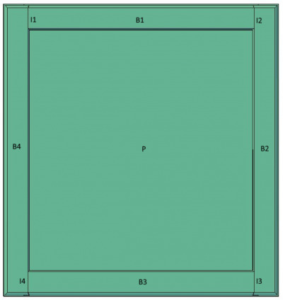
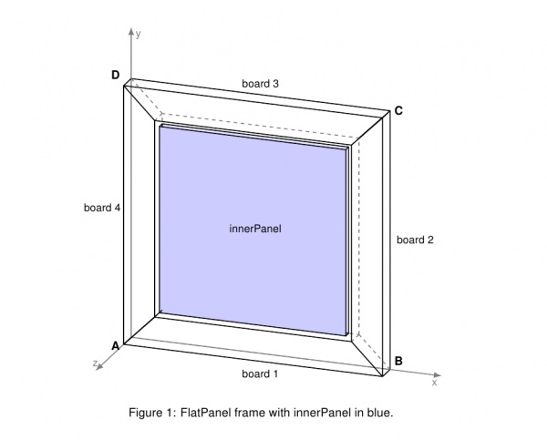
Figure 1: Schematic of a frame-and-panel furniture door, with labeles for the individual pieces.
Joint Types
The software currently supports two fundamental joint types for assembling the door frame components, and additionally, a monolithic frame that has no joints.
- Butt Joint: A joint where the end of one piece (typically a rail) is joined directly to the flat face of another piece (typically a stile) without any angled cuts. This is a straightforward, easy-to-manufacture joint. The program supports butt joints in different orientations.
In this software they are named VERTICAL and HORIZONTAL depending on preferred arrangement for output. More about this in Intersection Parameter
| Figure 1: Side View | Figure 2: Front View |
|---|---|
 |  |
| Caption | Caption |
| Butt joint generated with IG.Modell.Processor. This figure shows the side view of the joint assembly. | Front view of the butt joint. This figure provides a frontal perspective, demonstrating the visual seam. |
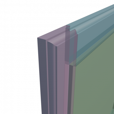
- Miter Joint: A joint where two pieces are joined at an angle, typically 45°, to form a 90° corner. Future implementation may implement other angles for miter joints. Both adjoining members (e.g., stile and rail) have their ends cut at complementary angles. This joint offers a clean, seamless look and it should support all kind of profiles. In this software Miter joint is named TRIANGLE.
| Figure 3: Miter Joint Side View | Figure 4: Miter Joint Front View |
|---|---|
 |  |
| Caption | Caption |
| Miter joint generated with IG.Modell.Processor | Front view of the miter joint |
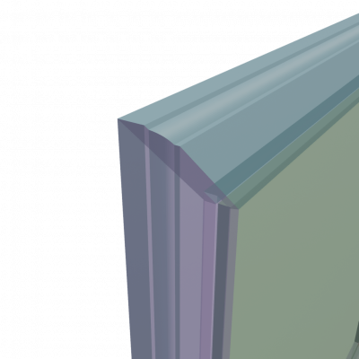
* Monolithic Frame with Separate Panel: In this construction type, the door frame (comprising stiles and rails) is manufactured as a single fused or milled piece, without mechanical joints between frame members. Although the frame appears to have traditional components (B1–B4), it is structurally continuous. The central panel (P) remains a separate piece, inserted into grooves in the frame to allow for natural movement. In this software Monolithic Frame is named SOLID.
| Figure 5: Monolithic Side View | Figure 6: Monolithic Front View |
|---|---|
 |  |
| Caption | Caption |
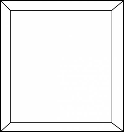
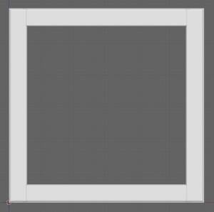
| Monolithic edge. There is no joint. | Front view of monolithic (solid) frame. |
Profiles
- Profile Definition: A profile defines the cross-sectional shape of a frame board pieces, panel (Solid) or Extrusion geometry, typically represented as a 2D outline (e.g., a groove, bevel, or decorative contour). Profiles are usually specified using SVG paths or parametric curves and are extruded along a path to form 3D geometry. In this software, the profile guides the shape of the extrusion for parts like stiles, rails, and panels. It will determine all values or output vertices in the Z direction (X direction) in Blender.
| Figure 7: Cross-Section Profile | Figure 8: Extruded Board |
|---|---|
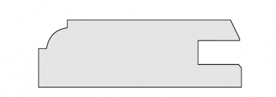 | 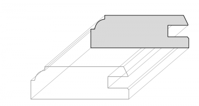 |
| Caption | Caption |
| Cross-sectional profile suitable for the stiles and rails (boards) of the furniture element. | Visual representation of the profile extruded into a board. Also this is the general result of Model Type: Extrusion 1.0 |
Positioning and Dimensions of Frame Components
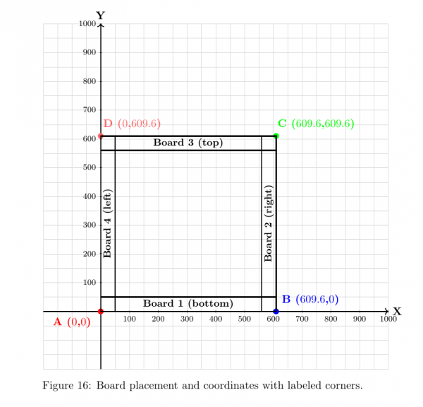
The frame is defined by four boards arranged in a rectangular pattern. The coordinate system defines each board's placement (see Figure Graphical Representation of Board Positions). The numeric values are always in millimeter.
- The coordinate system origin is at the bottom-left corner. This is always the position of the first board. It should be always set at $(0,0)$.
- Each board includes a required position $(x, y)$. The rotation angle is handled automatically by the program.
- Unit: is always set in millimeters. The examples uses for boards with dimensions of (609.6 mm = 24 inches).
- The boards currently could be only 4.
Example Board Placement Table
| Board | Position (x, y) | Rotation | Description |
| :—: | :—: | :—: | :— |
| 1 | A (0, 0) | 0° | Bottom board, placed horizontally left‐to‐right. |
| 2 | B (609.6, 0) | 90° | Right board, placed vertically upwards from bottom‐right. |
| 3 | C (609.6, 609.6) | –180° | Top board, rotated 90°, placed right‐to‐left. |
| 4 | D (0, 609.6) | –90° | Left board, placed vertically downwards. |
Please look on next page for graphic for more clarity.
Graphical Representation of Board Positions
| Figure 9: Board Placement |
|---|
 |
| Caption |
| Board placement and coordinates with labeled corners. |
Frame Dimensions graphic layout explanation:
The dimensions of the example frame on the figure are as follows:
- Width: 609.6 mm — The horizontal span of the frame, measured between points A–B and D–C.
- Height: 609.6 mm — The vertical span of the frame, measured between points A–D and B–C.
Example: JSON Configuration for Board Positions
"frame": [
	{
		"board": "1",
		"position": {
			"x": 0,
			"y": 0
		},
		"profile": "board"
	},
	{
		"board": "2",
		"position": {
			"x": 609.6,
			"y": 0
		},
		"profile": "board"
	},
	{
		"board": "3",
		"position": {
			"x": 609.6,
			"y": 609.6
		},
		"profile": "board"
	},
	{
		"board": "4",
		"position": {
			"x": 0,
			"y": 609.6
		},
		"profile": "board"
	}
]
This example shows how to define board positions using JSON. Each board is given a unique “board” ID and a 2D coordinate (x, y) to specify its placement within the frame layout. Boards align with the overall structure, occupying specific corners or edges of the rectangle.
Intersection Parameter ("intersection"): JSON Configuration for Joint Types
Overview
The global parameter intersection takes a string value and controls how all four boards meet when generating the 3D mesh. It applies to every board in the frame assembly and is required to be set in JSON format.
JSON Syntax for ''intersection''
intersection = "VERTICAL";
Example in Usage
{
	"intersection": "VERTICAL",
	"quality": 50,
	"uv": {
		"patchSize": 150,
		"uvorigin": "ORIGIN",
		"uOffset": 0,
		"vOffset": 0
	},
	"paths": [ … ],
	"frame": [ … ]
}
Supported Intersection Types
| Command | Description |
| :— | :— |
| VERTICAL | Vertical butt joint: boards meet edge-to-edge in the vertical direction. |
| HORIZONTAL | Horizontal butt joint: boards meet edge-to-edge in the horizontal direction. |
| SOLID | Monolithic frame with separate panel: frame and panel share one continuous piece. |
| TRIANGLE | Miter joint (45°): board ends cut at complementary 45° angles to form a seamless 90° corner. |
Details
- VERTICAL
Use for traditional stile-and-rail frames—boards abut along vertical faces.
- HORIZONTAL
Common in stacked or layered panel constructions—boards abut along horizontal faces.
- SOLID
Continuous geometry for frame and panel; panel remains a separate element without visible seam.
- TRIANGLE
Default 45° complementary cuts; future releases may allow custom angles.
Usage Notes
- Changing
intersectionmay requires changing profile as well if it is not build to be cut as butt joint. - Ensure profiles are compatible (e.g. TRIANGLE supports any profile shape).
- Default value is VERTICAL.
Visual Examples
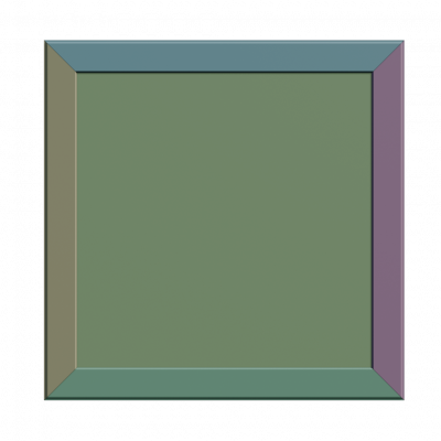
Butt Joints "HORIZONTAL" and "VERTICAL"
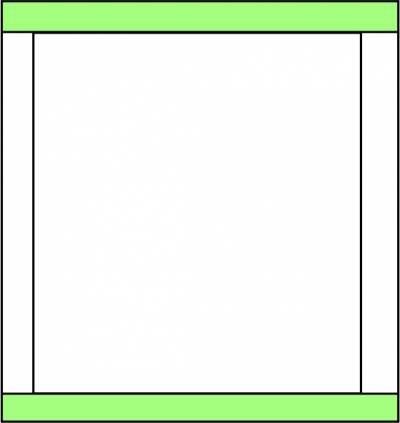
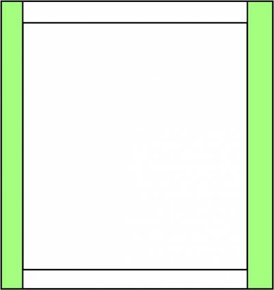
| Figure 10: Horizontal Butt Joint | Figure 11: Vertical Butt Joint |
|---|---|
 |  |
| Caption | Caption |
| Horizontal butt joint | Vertical butt joint (front view) |
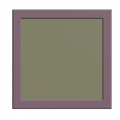
Solid and Miter Joints "SOLID" and "TRIANGLE"
| Figure 12: Solid Monolithic Frame | Figure 13: Miter Joint (Triangle) |
|---|---|
 |  |
| Caption | Caption |
| Solid monolithic frame | Miter joint (45°) |
Explanation of "innerPanel"{} Object Configuration
Below is a typical JSON fragment defining a complex-shaped innerPanel using the SOLID1_3 model:
"innerPanel": {
	"model": "SOLID1_3",
	"profile": "panel",
	"path": "placeholder_SOLID1_3",
	"trimProfile": "trim",
	"trimPath": "trimFrame",
	"offset": {
		"panel": {
			"translation": { "x": 0, "y": 0, "z": 0 },
			"dimensions": { "x": 0.0, "y": 0.0 }
		},
		"trim": {
			"translation": { "x": 0, "y": 0, "z": 0 },
			"scale": { "z": 0.01 }
		}
	}
}
"innerPanel": {
	"model": "SOLID1_1",
	"depth": 6.3,
	"offset": {
		"x": 5,
		"y": 5,
		"z": 2
	}
}
The innerPanel object supports three models via the innerPanel.model parameter:
- “SOLID1_1”: A standard prismatic (rectangular) panel. When this model is selected, the depth parameter is required if no profile is specified.
- “SOLID1_3”: A panel with a complex shape, defined by a custom path. This model requires the profile and path parameters.
- “EMPTY”: No panel is generated (a void). If this model is selected, all other parameters in the
innerPanelobject are ignored, and only the frame is generated.
Parameters for "innerPanel"
- offset (object):
Defines position and size adjustments for the panel and trim.
Contains two sub-objects:
- panel: transformations for the main panel
- translation: (object) —
x,y,zin millimeters; moves the panel relative to the frame center - dimensions: (object) —
x,yin millimeters; adjusts panel size (used for SOLID1_1)
- trim: transformations for the trim geometry
- translation: (object) —
x,y,zin millimeters; moves the trim - scale: (object) —
zvalue for additive scaling on the Z-axis
(e.g., 0.01 → scale of 1.01, useful for small overlaps)
Specifies how the innerPanel is centered relative to the frame before any offsets are applied.
- Type:
string - Default:
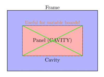
CAVITY - Required: No
Valid options:
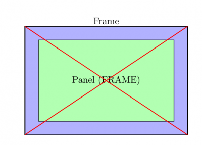
- FRAME — center the inner panel relative to the frame boundaries.
- CAVITY — center the inner panel relative to the cavity or cutout inside the frame.
Illustration:
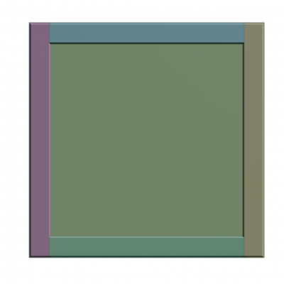
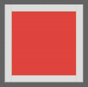
| Figure 14: Panel Centered to FRAME | Figure 15: Panel Centered to CAVITY |
|---|---|
 |  |
| Caption | Caption |
| Panel centered to FRAME — aligned with the outer edges of the frame. The red cross shows the frame center. | Panel centered to CAVITY — aligned with the inner empty space of the frame. The green cross shows the cavity center. Particularly useful if the frame boards have different widths. |
Note: This parameter determines the initial positioning of the panel. Subsequent adjustments using offset will move or resize the panel relative to this centered position.
- offset (object):
An object that defines positioning and dimension adjustments for the panel and its trim.
  It has a nested structure:
  * **panel:** Contains transformations for the main panel.
    * **translation:** An object with ''x'', ''y'', and ''z'' keys for moving the panel in millimeters relative to the frame's center.
    * **dimensions:** An object with ''x'' and ''y'' keys for adjusting the size of a **SOLID1_1** panel in millimeters.
  * **trim:** Contains transformations for the trim geometry.
    * **translation:** An object with ''x'', ''y'', and ''z'' keys for moving the trim in millimeters.
    * **scale:** An object with a ''z'' key for additive scaling on the Z-axis (e.g., 0.01 results in a scale of 1.01), useful for creating overlaps.
Note:
A legacy flat structure for offset with top-level x, y, z keys exists but is not recommended for new configurations.
Visual Examples for innerPanel Models
| Figure 16: EMPTY | Figure 17: SOLID1_1 | Figure 18: SOLID1_3 |
|---|---|---|
 |  | 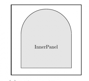 |
Caption: Visual representation of the EMPTY, SOLID1_1, and SOLID1_3 models for the innerPanel parameter. |
||
*Figure: Visual representation of the EMPTY, SOLID1_1, and SOLID1_3 models for the innerPanel parameter.*
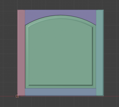
*Figure 2: flatPanel with SOLID1_3
Explanation of Subframes
The subframe structure is used to attach one or more secondary frames to a primary model. Each subframe is composed of individual pieces that are generated based on a specified model type, intersection logic, and profile path.
| Figure 25: Subframe Illustration |
|---|
 |
| Caption |
| FlatPanel frame with generated subframe in red. |
Type: array of objects
Required: No
Defines one or more subframes attached to the main model. Each subframe entry references a specific model type, intersection mode, profile path, and an identifier. Typically, four subframe pieces are defined per subframe.
- model
: Type: string Enum: `FLATPANEL1_0` Default: `FLATPANEL1_0`
  Specifies the model type used for the subframe.
* **intersection**
  : **Type:** ''string'' // **Enum:** `TRIANGLE`, `SOLID` // **Default:** `TRIANGLE` \\
  Defines how the subframe boards are intersecting each with one another.
* **profile**
  : **Type:** ''string'' \\
  References a path ID defined in the global `paths` array used to generate the subframe profile.
* **id**
  : **Type:** ''string'' \\
  Unique identifier for the subframe. This value is used to reference and name generated subframe elements.
* **offset**
  : **Type:** ''object'' // **Required:** No \\
  Defines an optional translation offset of the subframe in millimeters.
  ^ Offset Parameters ^ Description ^
  | **x** | horizontal offset (width) in mm. |
  | **y** | vertical offset (height) in mm. |
  | **z** | depth position offset in mm. |
* **pieces**
  : **Type:** ''array of 4 objects'' // **Required:** Yes \\
  Contains exactly four subframe pieces (see illustration above), each defined by a unique ID. Optional UV parameters overwrites may be provided for individual pieces.
  * **id**
    : **Type:** ''string'' \\
    Unique global identifier for the subframe piece (also used as the output mesh name).
  * **uv**
    : **Type:** ''object'' // **Required:** No \\
    Optional UV mapping settings for the piece.
    ^ UV Parameters ^ Description ^
    | **rotation** | Rotation of UV map in degrees. |
    | **patchSize** | Size of UV patch in millimeters. |
    | **uvorigin** | **Enum:** `ORIGIN`, `CENTER`. Defines UV anchor point. Default: `ORIGIN`. |
    | **uOffset** | UV translation offsets for U-axis in millimeters. |
    | **vOffset** | UV translation offsets for V-axis in millimeters. |