Model Type: Solid 1.4
The Solid 1.4 model is a versatile model type for creating fundamental 3D solid objects. Its primary function is to produce cuboid shapes with width and height (specified dimensions) and rounded edges via radius parameters and profile path. However, it can also generate more complex geometries by sweeping a 2D cross-section (profile) along a 2D trajectory (path). This dual capability makes it suitable for a wide range of components, from simple blocks to custom-shaped boards like a panel with arcs and similar.
 Figure 1: 3D illustration of the SOLID1\_1 model, showing dimensions, radii, and UV mapping.
 Figure 2: Isometric view of an SOLID1\_3 with arched panel example \textbf{path} with base rectangle ABCD and curved top.} ABCD describes frameWire path points . A1,B1,C1,D1 are generated points from extrusion depth taken from profil path.
- Purpose: To generate both simple and complex solid geometries, e.g., panels and boards.
- Supports:
- Primitive cuboids with optional edge beveling (see Figure 4 in source document).
- Advanced solids created by sweeping a
profilealong apath(see Figure 5 in source document).
- Recommended For: Creating base components, custom panels, and any solid form that can be described by a consistent cross-section along a path.
Methods of Generation
The model offers two primary methods for defining the solid's geometry:
- Primitive Solid: Defined using the
width,height, anddepthparameters. Edges can be rounded usingradius1andradius2. This is the most direct method for creating block-like shapes.
- Solid with Profile: Defined using the
width,height, andprofileparameters. Edges will be generated using parsed profile.
- Path-Based Solid: Defined by providing a
profileID and apathID from the mainpathsarray. The geometry is formed by sweeping the 2D shape of theprofilealong the 2D trajectory of thepath. This method is used for creating non-rectangular or custom forms.
Important Notes
- When
pathandprofileare specified, they take full precedence. The dimensional parameters (width,height,depth) and the radius parameters (radius1,radius2) will be ignored. - Both the
pathandprofilemust reference valid, closed 2D sketches defined within the top-levelpathsarray to produce a valid, watertight solid. - The
qualityparameter is crucial for achieving smooth surfaces on geometries that involve curves, whether from radii or from curved segments in apathorprofile.
This section describes the geometry generation behavior of the Solid 1.3 model, applicable in IG.Model.Processor version ≥ 1.3.0.100.
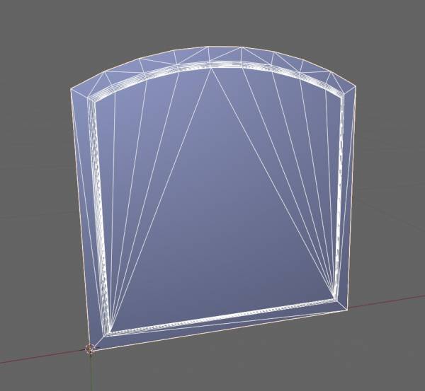 Figure 3: Solid with profile and path parameter from paths array
Setting profiles for Solid (SOLID1_3 or SOLID with width and height and profile definition)
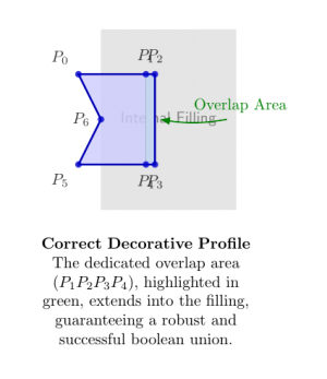
The core idea is that when a profile is swept along a path to create a frame, that profile's sketch should include a small, extra segment that extends inward. This extra piece creates a volumetric overlap with the internally generated “filling” shape.
This overlap is essential because it guarantees that the subsequent boolean “union” operation—which merges the frame and the filling into a single, solid object—will succeed without errors. Without this overlap, the two parts would meet at a perfectly aligned, “zero-tolerance” seam, which is a common source of failure for boolean algorithms due to mathematical floating-point inaccuracies.
Figure: Incorrectly Set Profile
This diagram shows a profile that stops exactly at the boundary of the internal filling. This creates a high-risk “coincident face” or seam, which can cause the boolean union to fail, resulting in rendering artifacts, gaps, or a non-watertight model.
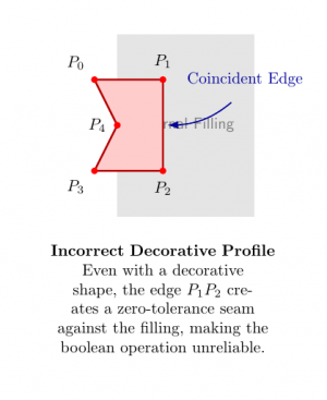
Figure: Correctly Set Profile
This diagram demonstrates the correct approach. The profile includes a small “lip” or “tail” that extends into the filling area. This intentional overlap ensures the boolean union is robust and reliable, producing a clean, solid final mesh.